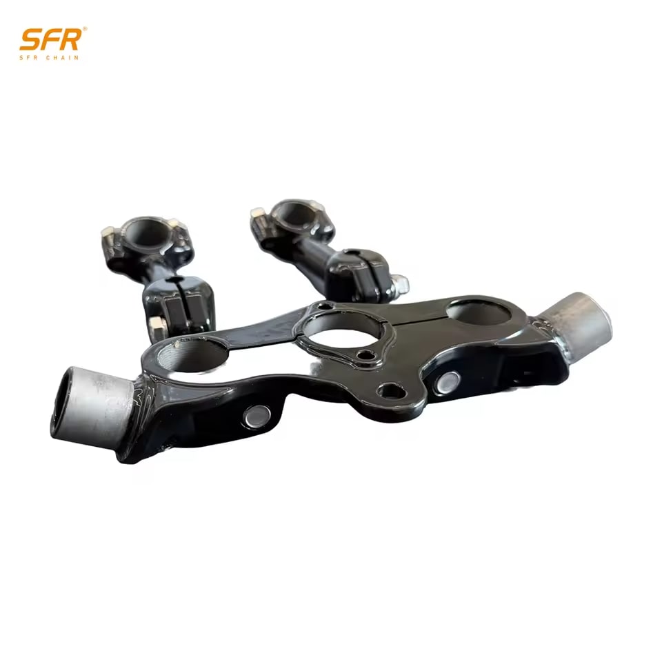
Triple Clamps

Bring the fork, steering, and handlebar mounting points together in a coordinated motorcycle front end. Explore how triple-clamp geometry affects the build, then view the Motomaxsfr steel CNC set for Harley Knucklehead-style custom projects.

Discuss Your Build

How the Upper and Lower Clamps Work Together

The upper and lower triple clamps hold both fork tubes in a fixed relationship to the steering axis. The steering stem passes through the frame’s steering head, while the two clamps keep the fork legs parallel and positioned as a pair. Turning the handlebar rotates this assembly and directs the front wheel.

The distance between the clamps supports the fork tubes at two points rather than one. When the clamp bores and fork positions align, the fork legs can move through their suspension travel without added bind from a twisted front-end assembly. The clamp pair also carries steering input between the handlebar, frame, and front wheel, so its geometry becomes part of how the motorcycle responds.

Risers place the handlebar above the upper clamp. Their position affects rider reach and the movement path of the controls, cables, wiring, and brake line. The featured Motomaxsfr product is listed as triple clamps and risers, bringing these two front-end functions into one product offering.

Geometry Shapes Steering and Component Position

Triple-clamp geometry determines where the fork and controls sit relative to the steering axis. Each dimension has a different effect on the completed motorcycle.

Design relationshipWhat it changes on the build
Steering stem and bearing interfaceConnects the clamp assembly to the frame and establishes its rotating axis. The stem length, bearing seats, and retention details must suit the steering head and bearings.
Fork clamp diametersMatch the upper and lower clamping locations on the fork tubes. Some forks use different diameters at the two locations.
Fork center spacingPositions the fork legs around the wheel, axle, fender, and brake components.
Clamp offsetPlaces the fork centerline ahead of the steering-stem axis. A change in offset changes trail when the rest of the chassis remains the same, which can change steering response and stability.
Riser and handlebar positionSets rider reach and affects tank clearance and the required travel of cables, wiring, and the brake line through the steering range.

These relationships must be considered together. A change intended to create more tank clearance or a different bar position can also affect control routing, while a different fork or wheel package can change the spacing and offset the front end requires. For a custom chassis, define the target steering geometry and component package before finalizing the clamps. For a retrofit, record the working interfaces and geometry before replacing them.

Installation Checks That Protect Alignment

Set the steering-head bearings and stem so the assembly turns smoothly without unwanted play. Insert the fork tubes at the intended height, then allow the fork, axle, and wheel assembly to settle into alignment before final tightening. Forcing the tubes into position or tightening an already twisted assembly can add friction to fork movement.

Use the tightening sequence and torque values confirmed for the supplied clamps, risers, and fasteners. Even clamping helps preserve alignment and avoids loading one side of a joint differently from the other.

After assembly, turn the handlebar from lock to lock. The tank, headlight, instruments, cables, wiring, and brake line must remain clear, and the throttle must return normally at both limits. Recheck free steering, bearing play, fastener security, and fork action before riding. A qualified motorcycle technician should inspect the completed steering assembly.

Prepare the Product Request

For a useful product confirmation or OEM/ODM discussion, send the following information in one request:

  • Motorcycle year and model, or the custom frame and steering-head reference
  • Steering-stem and bearing details
  • Upper and lower fork clamp diameters, fork center spacing, and target offset
  • Wheel, axle, brake, and fender combination
  • Handlebar diameter and riser arrangement
  • Quantity, destination, and any drawing or clear reference photos

State whether the build is a replacement, retrofit, or new custom front end. Motomaxsfr can then address the product configuration, price, production timing, included items, and installation information in the quotation or product confirmation.

Send Your Build Details

Discuss Your Triple-Clamp Project

Send your build reference and available measurements to discuss the listed Knucklehead-style product or an OEM/ODM request.

  • Phone: +86-0571-88620207
  • Correo electrónico: motomax@sfrchain.com
  • WhatsApp: +86-18857878411
  • Address: No. 271, Shuyun Road, Cangqian Street, Yuhang District, Hangzhou City, Zhejiang Province, People's Republic of China

Include the motorcycle or frame reference, key front-end dimensions, quantity, and destination.